Overview or Importance of Managing the Arc Flash Risk
Based on previous statistics, it's expected that the explosive energy released during arcing faults have sent more than 2,000 workers to burn centers per year. Many of these people were not properly warned of the magnitude of the hazard — if they were warned at all.
Although injuries from an arc blast are not as frequent as other injuries, their severity makes the costs to human life and to industry as a whole much greater. The monetary cost alone can easily exceed $1 million, and includes not only medical expenses, but the costs of equipment replacement, downtime and insurance.
While the potential for arc flash has existed for as long as plants have been powered by electricity, two factors have advanced arc flash safety many facilities.
The first is a greater understanding of arc flash hazards and the risks they pose to personnel. Research into arc flash and arc blasts, including testing conducted in Mersen's high-power lab, has helped quantify the various hazards they unleash. With this understanding, has come better equipment and protection methods.
The second is the continuing development of better standards, products and mitigation solutions. For example, NFPA70E continues to provide improved direction and guidance to better manage the risks of electrical hazards. A new edition of IEEE1584 was recently released with new equations and variables that now address the directional nature of arc development.
Improving Risk Management for Arc Flash Hazards
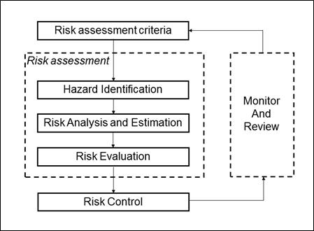
In the past two editions of NFPA 70E there has been an increasing emphasis on risk management principles when addressing the arc flash hazard. Annex F of NFPA70E provides good background information on Risk Assessment and Risk Control. The Risk Management Process diagrammed in Figure F.1 shows the role of risk assessment and risk control.
FIGURE F.1 Risk Management Process
The risk assessment includes hazard identification, risk analysis and risk evaluation. IEEE 1584-2018 would typically be used to estimate the potential magnitude of the thermal hazard of arc flash events. (see Changes to 1584-2018). NFPA70E provides Table 130.5(C) to help safety managers better estimate the likely the likelihood of an arc flash occurrence.
When using a hazard-based risk assessment, workplace hazards are identified and characterized and activities that might be affected by those hazards are identified including those actions possible by non-electrical workers. An organization would use this information to prioritize risk control decisions.
If your arc flash risk assessment determines that the objective of freedom from harm cannot be reasonably met by the risk controls that are in place, then a consideration of other risk control is required. The purpose of using a hierarchy of risk control methods is to help identify the most effective combination of preventative or protective measures to minimize the risk of arc flash injuries by all employees and on-site contractors.
A significant reduction in risk can be obtained by seeking “substitution” and “engineering” risk control methods that significantly minimize the likelihood of occurrence of harm or severity of harm. This is particularly effective when the information from hazard-based risk assessments are used by organizations when specifying electrical distribution equipment
Hierarchy of Risk Control Methods
In the 2012 cycle, NFPA 70E added an informational note, directing the reader’s attention to ANSI/AIHAZ10 for guidance in establishing a comprehensive electrical safety program. In 2015, another Informational Note was added to highlight the hierarchy of risk control methods of ANSI Z10. In 2018, this hierarchy of controls was added as Section 110(H)(3). The cover of NFPA 70E-2018 contains an image of this pyramid as emphasis of the importance of considering more effective ways (top of the pyramid) to minimize the potential for devastating injuries.
Notice in the risk assessment procedure of NFPA 70E 110.1(H) that companies must not only identify the magnitude of the hazard but must also assess the risks (likelihood of injury) and implement risk controls from this hierarchy. Note also that 105.4 states that Hazard elimination shall be the first priority. See below for information on the hierarchy of risk control methods.
NFPA 70E 110.1(H) is copied below to emphasize the role and importance of using the hierarchy of Risk Control Methods.
NFPA 70E 110.1(H) Risk Assessment Procedure. The electrical safety program shall include a risk assessment procedure and shall comply with 110.1(H)( 1) through 110.1(H)(3).
- Elements of a Risk Assessment Procedure. The risk assessment procedure shall address employee exposure to electrical hazards and shall identify the process to be used by the employee before work is started to carry out the following:
- Identify hazards
- Assess risks
- Implement risk control according to the hierarchy of rick control methods.
- Human Error: the risk assessment procedure shall address the potential for human and its negative consequences on people, processes, the work environment and equipment.
- Hierarchy or risk control Methods. The risk assessment procedure shall require that preventive and protective risk control methods be implemented in accordance with the following hierarchy.
- Elimination
- i. .
- Substitution
- Engineering controls
- Awareness
- Administrative controls
- PPE
- Elimination
Informational Note No. 1: Elimination, substitution and engineering controls are the most effective methods to reduce risk as they are usually applied at the source of possible injury or damage to health and they are less likely to be affected by human error. Awareness, administrative controls, and PPE are the least effective methods to reduce risk as they are not applied at the source and they are more likely to be affected by human error.
Recognizing that all risk cannot be eliminating, the risk control methods need to allow for human error and lead to risk magnitudes that are as low as practical and. The following discussion is aimed at helping you address the shortcoming of each method.
- Elimination: Eliminating hazardous is the best and most important way to keep workers safe. The best way to avoid an accidental exposure to a work place hazardous is to simply remove the hazard. Eliminating hazards can be done during the design of the system or removed prior to workers being exposed.
- Substitution: Some a load can’t simply be disconnected. When eliminating a load can’t be done in some cases the hazard can be substituted with a lessor hazard.
- Engineering controls: Designing system to reduce worker exposure in a modern solution to increasing workers safety. Engineering mitigation removes workers access to hazardous energy by designing a system where a worker doesn’t have access to energized components or hazardous levels of energy. Reducing or eliminating by either switching methods that remove access to energized components or through methods that reduces the amount of energy a worker can be exposed to in case of a fault such as fuses.
- Awareness: Creating an informed environment for workers helps eliminate the threat of accidentally being exposed to hazardous energy. Educating the worker on locations of hazardous access points with in a facility reduces the workers potential exposure to hazards. Simply being aware of hazardous energy and it’s affects provides a safer work environment.
- Administrative controls: Management creating procedures that employees limit the amount of energy works have access to. This is done by enforcing a LOTO and switching procedure eliminating access to hazardous energy.
- PPE: Personal Protective Equipment is the last line of defense against being exposed to hazardous energy. PPE should never be your only protection against hazardous energy.
Show less
Addressing High Incident Energy due to Low Fault Currents
If the arc current (Iarc) through the protective fuse is below the Threshold Current of the fuse, the duration of the arc flash will be determined by the total clearing curve (tcc) of the fuse. Depending on the magnitude of Iarc, this could be several cycles or several seconds.
When the clearing times are so long that the predicted incident energy is greater than your company’s desired limits, changes to the fuse selection should be considered. The following examples would be considered solutions that would that use risk control elements that are higher on the hierarchy of the risk controls pyramid of 70E.
Replace fuses with UL Class RK1 fuses to lower incident energy.
Arc flash incident energies can often be significantly reduced by simply replacing UL Class RK5, Class K, and Class H fuses with A6D UL Class RK1 fuses. This is an easy and inexpensive solution, since the A6D fuses fit into the same fuse holders. Upgrading to A6D Class RK1 fuses can reduce arc flash energies because these fuses have lower let-through energies in their current limiting range and lower current limiting thresholds. Please note that Class H fuses are not current limiting and have a very low interrupting rating. If there are any of these left in your system you should plan to retire these as soon as safely possible.
- Download Tech Topic for more details
Reduce Ampere Ratings to lower incident energy.
When the arcing fault current is less than the fuse’s threshold current, the incident energy will depend on the clearing time of the fuse and can be higher than desired. Within the same fuse class, current-limiting fuses that have lower ampere ratings will have lower threshold currents. This wider range of current-limiting operation can be used to reduce arc flash energy in applications where available fault currents are low relative to the existing fuse’s threshold value.
Mersen has two solutions that have proven to be beneficial for these situations. Mersen’s A4BQ class L fuse has very low thresholds and can be easily downsized without any reducer hardware. Likewise, Mersen’s new A6D REDUCER fuse allows you downsize a frame size without the need for fuse reducers. For example the A6D400/600R fuse has a 400A fuse elements contained in a 600A frame.
Consider non-time delay fuses.
If the arcing fault current is less than the AmpTrap2000 fuse’s threshold current and the incident energy determined by the clearing time of the fuse read from the time current curve of the fuse, a change in curve shape may be helpful. Within the same fuse class and ampere rating, non–time delay current-limiting fuses will have shorter clearing times in low fault current region and can be helpful in reducing incident energy to acceptable levels. Also, these fuses will have a lower threshold current for the same ampere rating and fuse class. This wider range of current-limiting operation can be used to reduce arc flash energy in applications where available fault currents are low to under 1.2 cal/cm2. Consult with Technical Services for guidance in sizing where temporary overloads (e.g.motor starting currents) are expected on the circuit.
Semiconductor fuses have also been used for their lower threshold currents. Contact Technical Services for guidance on selecting and sizing these fuses for reliable operation.
Reducing LV Switchgear incident energy to below Extreme Hazard
Arc flash incident energy calculations are frequently above 40 cal/cm2 for equipment connected directly to the secondary side of power transformers due to existing electrical system designs and transformer fuse protection practices. Many companies use this value as the upper limit for energized work. Consequently these companies must now insist on outages to perform routine tasks on this equipment. When the equipment is switchgear feeding large processes, the downtime cost of a task such as racking in and closing a power circuit breaker can be tens of thousands of dollars In some cases, it is possible to reduce energies below 20 cal/cm2 and maintain reliable operation by using a fuse with different time current characteristics.
Rethink Control Panel Design
With the addition of Article 409 in 2005, the NEC began requiring the labeling of Industrial Control Panels with their (SCCR Short Circuit Current Rating). Other related articles were likewise changed. Inadequate SCCR could lead to a potentially hazardous arc flash condition for a short circuit downstream of the panel.
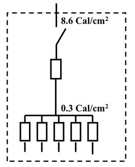
While changing designs to get higher SCCR ratings, designers have also sought ways to minimize arc flash risks for workers who interact with the control panels. Although using fuse protection for control panels could achieve 100kA SCCR, traditional designs like that shown below could still have a high incident energy calculation. In this example, the incident energy at the incoming line terminals was calculated to be 8.6 cal/cm2 based on the upstream overcurrent protective device with the characteristics of the power system. Even though the main fuse could limit the incident energy to the value of 0.3 cal/cm2, industry practice is to label the panel with the highest value calculated for the enclosure. In this case, the installer would generate an arc flash label with 8.6 cal/cm2 for this panel. When required by company policy, workers would then to wear PPE with an arc rating greater than this value.
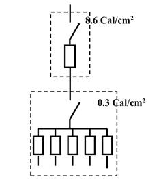
A simple change to protection philosophy can result in a panel with a much reduced arc flash risk. Placing the main fuse protection inside a separate enclosure as indicated below, would result in a panel with a 0.3 cal/cm2 incident energy calculation. With this approach, there is less risk and a lower hazard level for workers that may have to open the door to the panel while energized. This is an example where considering the hierarchy of risk controls can lead to a safer work environment.
If you are using UL508A Supplement SB to calculate SCCR and to make labels, the following section provides guidance on how to label the panel when using this approach:
SB5.1.3 An industrial control panel marked with a high fault short circuit current rating and is not provided with the required feeder circuit protective device as specified in the SB4.3.4 shall be marked with the type and size of feeder circuit protection required to be installed in the field. This marking shall be included as part of the marking in SB5.1.1.
Reducing Arc Flash Risks For MCCs
Increasing concern for arc flash safety has grown to include both operators of electrical equipment as well as electrical workers. Internal arc faults can blow open doors of low voltage equipment including motor control centers (MCC) that have been properly installed[1]. Should this occur when an operator is interacting with the equipment, the worker can very easily be exposed to the hazards of arc flash.
Electrical safety programs must ensure that all workers who interact with electrical equipment are protected from arc flash hazards to a level of risk acceptable to the organization. Arc resistant MCCs are a good option for minimizing the likelihood of operators being exposed to the arc flash hazard when interacting with the equipment when it is properly closed. An arc resistant MCC’s rated with an A4BQ Class L main fuse should not have special venting requirements compared to other approaches.
Even with an arc resistant MCC that will protect workers against arc flash hazards when the door is closed, consideration should be given to the required level of PPE worn by electrical workers who interact with the MCC while it is energized and the door open. An incident energy goal of less than 1 cal/cm2 to reduce the risk of serious worker injury can usually be obtained throughout the life of the MCC with the proper selection of branch and feeder fuses.
Download Tech Topic TT-SP2-001 for guidance on fuse selection to:
- Obtain optimum arc flash protection of anyone interacting with the MCC.
- Obtain optimum short circuit protection of equipment and components
- Maintain continuity of power to critical loads with simple coordination guidance.
- Ensure long and reliable life.
Refer to the paper “Exposed to the Arc Flash Hazard” for more information on containing arc flash hazards.
Show less