Arc Flash Hazards
The severe hazards created by arcing faults in today's industrial power systems arise from two factors: the tremendous amounts of power that can be delivered to such arcs and the workers' close proximity to them.
When the arc is being established, current begins passing through ionized air generating massive quantities of heat in the plasma. Large volumes of ionized gases, along with metal from the vaporized conductors, can be explosively expelled. As the arc runs its course, electrical energy continues to be converted into extremely hazardous energy forms.
Hazards include:
- The immense heat of the plasma and radiated heat
- Thermoacoustic shock wave
- Ejected molten droplets of conductor material
- Shrapnel
- Large volumes of toxic smoke
- Extremely intense light
- Contact with energized components.
Heat Hazard
Tests have shown that heat densities at typical working distances can exceed 40 cal/cm². Even at lower levels, conventional clothing ignites, causing severe, even fatal, burns. At typical arc fault durations of less than one second, a heat density of only 1.2 cal/cm² on exposed flesh is enough to cause a second-degree burn. Even workers not in the plasma can be burned from the intense heat radiated beyond typical working distances.
As discussed under electrode configuration, tests have shown that an object in the expanding plasma cloud can be exposed to a higher level of heat than predicted with the IEEE1584-2002 model. In addition to the convective heat transfer from the plasma, the object can be directly exposed to the molten metal ejected from the electrode tips and radiated heat from surrounding plasma.
The amount of heat absorbed varies with the method of heat transfer and receiving surface properties. For example, the amount of heat transferred from a mass of molten copper to a surface area would be greater if it adhered to the object instead of contacting it for a brief time.
Other Hazards
Thermoacoustic Shock Wave: As the conductive element that caused the arc is ionized, the power delivered to the arc fault rises rapidly. This corresponds to a rapid rise in surrounding pressure. The resultant shock wave can create impulse sound levels well beyond OSHA's allowable limits. Forces from the pressure wave can rupture ear drums, collapse lungs or cause fatal injuries.
Molten Metal: At high fault current levels, plasma jets are formed at the electrodes. Vaporized and molten electrode material is ejected at high velocity from these jets, reaching out several feet. Since the molten metal is typically over 1000° C, it is a potential ignition source for conventional clothing and other surrounding material.
Shrapnel: The force of the explosion also causes a significant amount of shrapnel to be accelerated away from the source. These particles can impact a nearby worker at high velocity, resulting in physical trauma.
Blinding Light: As the arc is established, an extremely bright flash of light occurs. The light can cause immediate vision loss. Although the vision loss is usually temporary there may be an increased potential for future vision deterioration.
Toxic Gases: As plasma is driven further from the arc, it cools rapidly. Plasma components can combine to form toxic byproducts such as copper oxides. This ‘plasma dust’ can be deposited onto components throughout the involved electrical equipment posing future hazards to the workers assigned to repair and clean up the equipment. This conductive dust, if not removed, could also lead to a future arc flash if not removed from insulating material.
Contact with Energized Components The explosive nature of an arc fault increases the possibility that an energized conductor or components will make contact with workers in the area.
Potential Causes of Arc Flash
An arc flash can be caused a number of ways, including:
- Accidental contact with energized parts
- Inadequate short circuit ratings (e.g. SCCR and AIR)
- Tracking across insulation surfaces
- Equipment failures
- Tools dropped on energized parts
- Wiring errors
- Contamination, such as dust on insulating surfaces
- Corrosion of equipment parts and contacts
- Improper work procedures
As you would expect, proper procedures, tools and maintenance can prevent most arc flash situations from occurring. Design improvements and substitution of better protection can minimize the magnitude of the arc flash hazard and/or the likelihood of worker injury.
Directional Nature of Arc Development
Unrestricted high-current arcs move according to magnetic forces to increase the area of the current loop. Currents flowing in the opposite direction in parallel conductors give rise to forces that drive the arc away from the source to the end of the conductors where they typically burn off the tips of electrodes (bus bars).
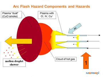
The behavior of a 3-phase arcing fault in equipment is very chaotic, involving rapid and irregular changes in arc geometry due to convection, plasma jets and electromagnetic forces. Arc extinction and re-ignition, changes in arc paths due to restriking and reconnection across electrodes and plasma parts and many other effects add to this chaotic nature and make it difficult to create equations for accurate predictions of its properties (e.g. impedance). Although it does not capture this chaotic behavior, Figure 1 demonstrates an arc’s general directional nature. The alternating 3-phase current creates successive attractive and repulsive magnetic forces, dramatically moving the plasma jets which feed an expanding plasma cloud. The cloud is driven outward, away from the tips, creating “plasma dust” as the highly energized molecules in the plasma cool, then recombine into various materials. The molten electrode material ejected off the tips are also in this flow. Figure 2 shows a frame of a high speed video at 4ms into an arcing fault with the HOA configuration as viewed from the perspective of arrow 1 in Figure 1.
Figure 1: The directional nature of an arc; this depiction does not reflect chaotic behavior.
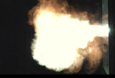
Figure 2: The plasma development at 4 ms into a 44kA fault with a HOA configuration
Show lessElectrode Configuration
Research performed at Mersen’s High Power Test Laboratory uncovered electrode configurations that project significantly more heat energy out of enclosures toward worker locations than was predicted by the IEEE 1584-2002 Guide. To simulate components found in low-voltage electrical equipment, various setups were created for controlled testing. Heat was measured and compared with predictions of IEEE 1584-2002 for switchgear. Results of these comparisons were published in two IEEE papers. [6][7] Configurations that forced the arc’s plasma jets outward toward the worker produced higher heat measurements than predicted by IEEE 1584-2002 equations when studied at typical working distances of 18 inches.
All arrangement described below are variations of an arrangement described in IEEE 1584-2002. These test setups used a 508mm x 508mm x 508mm steel box with one side open. 3-phase arcing tests were conducted at 208V, 480 V and 600V. The gap between electrodes was 32mm (1.25in) and the distance between the electrodes and the back of the box was 102mm (4in). Incident heat energy was measured with an array of 7 or 9 copper calorimeters as described in the IEEE 1584 test procedure. Photographs of the arcs were captured from video taken with a FASTCAM high-speed camera, at up to 10 000 frames per second.
Vertical Conductor Configuration in an Enclosure (VCB)
In the vertical configuration setup used in the IEEE1584-2002 test program, the electrodes entered the 20”x20”x20” box from the top. The electrode tips were ‘open’ and 10” from the bottom of the box as shown in the figure below. This setup simulates equipment where bussing is vertical and open-ended such as the ends of bus bars in a power panel.
This configuration is referred to VCB (Vertical Conductor in a Box) in IEEE 1584-2018.
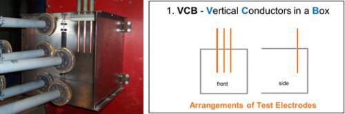
Figure 3: Vertical Conductor in a Box test configuration (Open Tip Electrodes).
The arc development, similar to that described for Figure 1, will be downward toward the bottom of the box in this case. As described in [2], there is an outward convective flow due to the thermal expansion of the gases and not magnetic forces. Photo of the arc development is shown is shown in Fig.4. Tests at the Mersen lab resulted in heat measurements consistent with the predicted levels of IEEE1584-2002.
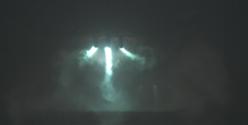
Figure 4: Front view of arc development from vertical test 3ms into event.
Vertical Conductor Configuration without an Enclosure (VOA)
In this vertical configuration setup, there is no enclosure to focus the downward plasma flow towards a worker. For those installations where the analyst is convinced that the worker would never be in the flow shown in Fig 1 and the figure 4 photo, then this configuration would be applicable. This configuration is referred to VOA (Vertical Conductor in Open Air) in IEEE 1584-2018. If it is possible for the worker to be in the plasma flow then the HOA configuration discussed later would be applicable.
Vertical Conductor Configuration in an Enclosure with an Insulator over the tips (VCBB)
In the configuration shown in Fig 5, the electrodes of the vertical setup are “terminated” into a block of insulating material (barrier). The block was referred to as a barrier since it blocked the arc from creating plasma jets off the electrode tips as shown in Figure 1. This setup represents conductors connected to equipment fed from the top. This configuration is referred to VCBB (Vertical Conductor in a Box with a Barrier) in IEEE 1584-2018.
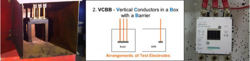
Figure 5: Test configuration simulating the line side connections of top fed equipment.
With the barrier in place, the arc’s downward motion is halted and plasma jets are formed along the plane of the insulating barrier’s top surface (i.e. perpendicular to the plane of the electrodes). This significant finding is demonstrated in the Fig 6. This photo in Fig. 6 shows the results of a test identical to the VCB test discussed above but with an insulating block attached over the tips of the conductors.
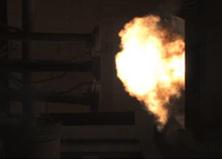
Figure 6:. Side view of arc development from VCBB tests at 42kA and 480V event.
This direction of the plasma flow shows the possibility of higher convective heat transfer toward workers than the open vertical setup. The barrier test results were always greater than the IEEE1584-2002 predictions-sometimes 50% more than the prediction. The barrier configuration also ejected significantly more molten electrode material. With this configuration, because the magnitude of the arc current is higher, incident energy can be less if the clearing time is significantly lower.
Refer to the paper “Effect Of Insulating Barriers In Arc Flash Testing” for more information on the VCBB configuration.
The photo in Figure 7. shows a side view of arc development along the plane of the barrier in a setup without side panels. Notice that the plasma flow is both outward and back toward the back plane of the test fixture. The plasma and gases are shown reflected off the back panel through the conductors. This increased ionization between the conductors is believed to contribute significantly to the sustainability of arcs on 208V systems. Research at the Ferraz Shawmut test lab showed that arcs could be sustained for fault currents as low as 4kA for 208V system under certain test conditions[N].
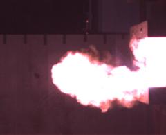
Figure 7: Side view of arc development from barrier tests 4ms into a 42kA, 480V event.
- Download IEEE Paper #6
- Download IEEE Paper #2
Horizontal Conductor Configurations
Horizontal Conductors in an Enclosure: A configuration that deserves serious consideration is the horizontal electrode configuration in an enclosure. This setup simulates equipment where bussing is open-ended, but pointing toward the front of the enclosure, like that in the equipment of Figure 8. This configuration is referred to HCB (Horizontal Conductor in a Box) in IEEE 1584-2018.
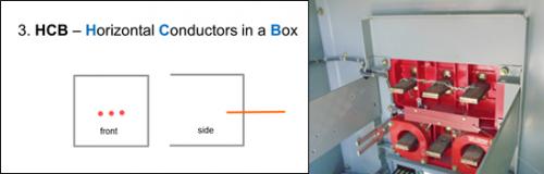
Figure 8: HCB Test configuration simulating equipment with rear entry conductors.
When the electrodes are horizontal and fed from the back, the arc development is very similar to that described for Fig. 1 and is shown in the photo in Fig. 9. In this test, the electrodes entered from the rear of the box and were 104 mm (4in) from the back of the box. Although the plasma jets are not visible there is a very strong outward plasma flow that is focused to the opening of the enclosure by the walls of the enclosure.
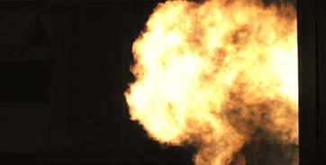
Figure 9: Side view of arc development being projected out of the front of the box (600V; 44kA)
All tests with this configuration resulted in heat measurements significantly above the predicted levels with IEEE1584-002. In some case, the incident heat energy density was near three times that of the vertical tests. Of equal concern is the fact that arcing currents were below predicted levels for this configuration. In some applications, clearing times will be significantly longer than expected if the arcing current is too low to operate the short circuit element of the upstream overcurrent protective device (OCPD). In these applications, the increase in arc flash heat energies will be far greater than the differences obtained in tests with a fixed clearing time.
Horizontal Conductors without an Enclosure: Another configuration that deserves serious consideration is the horizontal electrode configuration without an enclosure. This setup simulates equipment where bussing is open-ended, and not recessed in an enclosure, like the end of a horizontal bus in switchgear when the side panel is removed for an infrared photo. This configuration is referred to HOA (Horizontal Open Air) in IEEE 1584-2018.
In the picture of Figure 10, the electrodes were brought to the front of the test box, clearly showing the plasma flow from the tips of the electrodes. With this placement of the electrodes, the enclosure had no focusing effect and the incident heat energy is expected to be less than the HCB configuration.
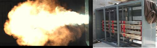
Figure 10: Side view of plasma flow at 8 milliseconds into a 44kA 600V arcing event with the HOA test configuration.
Refer to the paper “Effect Of Electrode Orientation In Arc Flash Testing” for more information on the HCB and HOA configurations.