Overview of Current Limitation
Low Voltage current limiting fuses, such as those listed to the UL Class J or RK standard, must clear a single phase short circuit current in less than one half cycle in its current limiting range. Since the fuse element must also melt in less than the first quarter cycle, it prevents the fault current from reaching its first peak. This reduction of fault current magnitude and duration can dramatically reduce the electrical energy delivered to an arc fault as evidenced by the very low prediction of incident energy in this range using IEEE1584 equations.. Also, by melting before the peak power of the three phase fault is reached, current limiting fuses can also be considered peak power limiting.
Current limitation is one of the most important features of today's fuses. By isolating a faulted circuit before the fault current has sufficient time to reach its maximum value, a current-limiting fuse can:
- Limit the destructive heating effects of arcing faults.
- Limit peak power delivered to arcing faults and its potential consequences.
- Minimize (or prevent) damage to equipment in the faulted circuit by limiting the rapid heating of components and destructive electromechanical forces.
- Reduce the magnitude and duration of the system voltage drop caused by fault currents by quickly isolating the faulted circuit.
- Minimize downtime, since current-limiting fuses provide superior coordination under short circuit conditions.
Key terms
- Current limiting fuse
- Threshhold current
- Peak Let through current
- Effective rms let through current
- Current Limitation
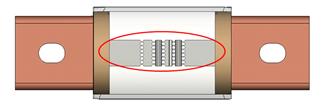
Current Limiting Operation. The short circuit element of a fuse, made of strips of copper or silver with regions of reduced cross-sectional area called notches (Figure 1), is enclosed in an insulating tube filled with pure quartz sand. Designed to carry normal load currents without melting, current limiting operation begins at the initiation of a short circuit greater than its threshold current. As the short circuit current starts to rise, the temperature of the notches begins to rise very quickly. When the notches melt a number of small internal electric arcs are produced in the notch zones. The increasing impedance of the series arcs halts the rise of the fault current and causes the fault current to be rapidly reduced to zero and the arcs are rapidly extinguished.
Figure 1: Current limiting fuse notches
Figure 2 illustrates the operation of a fuse interrupting a short circuit fault current in an ac circuit. During the pre-arcing (melting) period the current follows the prospective current wave and the voltage drop across the fuse is quite low. When the fuse element melts and internal arcing begins the voltage across the fuse increases rapidly and the current is forced to zero well before the natural zero crossing of the available current wave as shown in the figure. Thus the two requirements for current limitation are met; the peak instantaneous current (Ip) allowed by the fuse is less than the peak of the prospective current and the duration of the arc is less than ½ of an electrical cycle. Within the same UL fuse class, larger ampere ratings will ‘let-through’ higher currents.
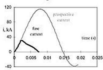
Figure 2: Performance of a current limiting fuse
Note that low voltage current limiting fuses are tested under worst-case short circuit test conditions (i.e., closing angle of 0° at 15% power factor) to evaluate performance under a worst case fault condition. Under these test conditions, the maximum peak instantaneous current of 2.3 times Irms.will create the highest electromechanical forces in equipment.
The degree of current limitation provided by a fuse is measured two ways — peak let-thru current (lp) and I²t. Maximum allowable lp and I²t values are specified in UL standards for all UL Listed current-limiting fuses, and are available on all semiconductor fuses.
Manufacturer-published data for current limiting fuses include Ip and effective rms current. The current limiting performance can be communicated with let-through tables, let-through charts or equations relating Ip to the prospective fault current. Since the output of these methods is the peak value of the resulting limited waveform, the fault current that would produce the same Ip without any current limitation is referred to as the rms let-through current.
Energy Limitation
Since current limiting fuses can reduce both the magnitude and duration of a fault current, there is a dramatic reduction in the first half cycle energy delivered to an arc fault. Interruption can occur before the potential peak power of the fault is reached. This energy limitation is demonstrated in Figure 3 where the power waveform from a seven cycle three phase arc fault is compared to the power waveform (highlighted in red) of the same arc fault circuit when protected by a 400A UL Class J fuse. The seven cycle event delivered 1130 kWs to the arc.
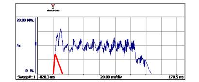
Figure 3: Power waveforms for arc fault tests (480V; IBF 35.4kA)
Energy was limited to 19 kWs with the 400A Class J fuse and the measured incident energy was less than 0.3 cal/cm². Note that the ½ cycle arc energy was less than 1/14th of the 7 cycle event for this fuse class. The additional 75% reduction in electrical energy delivered is due to the limitation of the current as well as the duration.
This dramatic reduction in arc energy makes it more likely that arc fault damage can be quickly repaired and equipment placed back into service.
When larger ampere ratings of the same UL class are used, energy delivered to arc faults can be slightly higher since the larger fuses will have slightly higher let-through currents. Also, since the larger ampere ratings have higher threshold currents, considerations must also be made for circuits with low arc fault currents.
This energy limitation enables Class J, RK1, T and L fuses to reduce incident heat energy from an arc flash to very low levels. The incident energy performance of an A6D600R fuse can be seen in the plot of Figure 4. Note that the estimated incident energy for the parameters defined below would be below 1.2 cal/cm² for available fault currents from 12kA to 106kA. (Calculations were made using IEEE 1584-2018 equations and A6D600R let through currents above the fuse threshold).
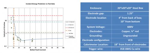
Figure 4: Plot of Incident energy calculations for A6D600R
Show lessPower Limitation
Since current limiting fuses can interrupt the arc fault before the potential peak power of the fault is reached, the pressure increase within closed equipment can be reduced. If the enclosure remains closed during an internal arc fault the risk of an arc flash exposure to an employee near the equipment can be reduced. Such a reduction is shown in the two videos of tests of an MCC with an internal fault. The first video is that of a test with an overcurrent protective device that cleared in in 2-1/2 cycles and no power limitation. The second video is a repeat of the first test but with power limitation from the very current liming A4BQ800. More details are available in the papers listed below.
Refer to the paper “Exposed to the Arc Flash Hazard” for more information on containing arc flash hazards.
Download “Exposed to the Arc Flash Hazard” paper
1584 Calculations with Let Thru Current
IEEE 1584-2018 Incident Energy Calculations Can Use Let-Thru Current
If the arcing current is greater than the threshold of the current limiting fuse protecting the circuit, the calculation of incident energy can use the ‘effective’ arc current derived from the let through charts of the fuse. See the discussion below on how to obtain the let through current for an arc fault for an arc flash calculation.
Using Peak Let-Thru Charts to derive effective rms let through current
Let through charts like that of Figure 5, plot the expected instantaneous peak let-through current (Ip) versus the prospective current. The X axis [1] is prospective (or available) fault current in rms symmetrical kiloamps and the Y axis [2] is Ip in kiloamps.
The fuse performance of the A6D600R is a combination of line 3 (until the intersection of line 4) and line 4 from the intersection up through its interrupting rating of 200kA.Line 3 represents the maximum peak instantaneous current of 2.3 times Irms without current limitation discussed earlier.
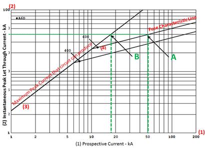
Figure 5 A6D400R AND A6D600R Let through Chart
To determine the Ip for the A6D600R RK1 fuse with a 50kA prospective fault, start on the x-axis in figure 4 at 50kA and go up to point A on the fuse characteristic. Reading to the left on the y-axis, the Ip is 40kA. Without current limitation, the Ip would be 115kA.
It has been customary to relate the rms value of the rough triangle waveform (of figure 2) to its peak value by dividing Ip by 2.3. This relationship implies that the rms value of the triangle wave is equivalent to a periodic waveform equivalent to this quotient (value). This is equivalent to moving to Point B from Point A and dropping down to the y-axis and reading 17kA rms. This value is referred to as effective rms current.
Using Peak Let-Thru Tables
Although the characteristics of current-limiting fuses are represented in peak let-thru charts, peak let-thru tables are easier to use.
Based on peak let-thru charts, the tables reflect fuse tests at 15% power factor at rated voltage, with prospective fault currents as high as 200,000 amperes. At each prospective fault current, let-thru data is given in two forms— Irms and Ip.
Where Irms is the effective rms current and Ip is the maximum peak instantaneous current passed by the fuse, the lp let-thru current is 2.3 times Irms. This relationship exists between peak current and RMS available current under worst-case test conditions (i.e., closing angle of 0° at 15% power factor).
Using let-thru tables saves time and reduces the possibility of errors. The tables are also helpful when comparing the current-limiting capability of various fuses.
Click on the fuse name to view its peak let-thru table:
- Amp-Trap 2000® A4BQ Class L Fuse
- Amp-Trap 2000® AJT Class J Fuse
- Amp-Trap 2000® A6D Class RK-1 Fuse
Determining Ip with an Equation
In addition to tables and let through charts, the let through characteristic can be described by an equation as shown below. Each current limiting fuse would have its own value for K. The equation only applies to the range of currents on the fuse characteristic line (see Figure 4).
Ip = K *〖(I"prospective)" 〗^(1/3) (1)
Fuses Recommended for Reducing Arc Flash Incident Energy
The fuses that we typically recommend for arc flash energy reduction are UL Listed branch circuit fuses with the highest degree of current limitation. The fuses shown here have had excellent results in laboratory tests and in the field, limiting arc flash incident energies to very low values for arc fault currents within their current-limiting range.
To see how well these fuses limit incident energy, use our calculator. To discuss how Mersen fuses can help reduce arc flash hazards in your facility, email us or call our Technical Services department. Our Technical Services Department is ready to help you with your for more challenging applications.
Amp-Trap 2000® A4BQ Class L Fuse
Originally designed for applications greater than 600 amperes, our A4BQ offers an interrupting rating of 300 kA and a unique design that delivers excellent performance in arc flash situations. The hole pattern and blade size on this fuse are designed such that downsizing ampere frame size can be accomplished without the need for any reducer hardware. Ampere ratings down to 100A are now available for arc flash mitigation.
Amp-Trap 2000® AJT Class J Fuse
The ideal choice for new applications of 600 amperes and less, AJT offers excellent current-limiting performance for short circuits and time delay for overloads. Because the unique Class J dimensions prevent improper substitutions this is the ideal choice for new applications to minimize risks due to the human error of improper fuse substitution.
.
Amp-Trap 2000® A6D Class RK1 Fuse
The ideal substitution for upgrading existing applications of 600 amperes and less for arc flash mitigation, the A6D offers excellent current-limiting performance for short circuits and time delay for overloads. Its dimensions allow for simple upgrades of existing Class H, Class K and Class RK5 fuses. Customers who upgrade for arc flash mitigation should consider Mersen’s free Fuse Control Service to obtain guidance on preventing the possible human error of mis-substitution with lesser rated fuses.
Amp-Trap 2000® A6D Class RK1 Reducer Fuse
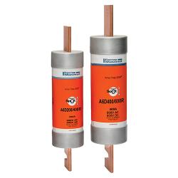
When changing to A6D UL RK1 fuses is not enough to reduce incident energy to acceptable levels, consider reducing the ampere rating as well. If the load is not near the capacity of the circuit, it is acceptable to use an ampere rating lower than the rating of the circuit. The new A6D Reducer Fuse allows you to downsize a frame size without the need for fuse reducers. For example the A6D400/600R fuse has a 400A fuse element contained in a 600A frame
The ideal choice for upgrading existing applications of 600 amperes and less, the A6D Reducer Fuse offers the same excellent current-limiting performance for short circuits and time delay for overloads. Its dimensions allow for simple upgrades of existing Class H, Class K and Class RK5 fuses.